Quantcast
Channel: Tip of the Day – Cadimage Blog
Viewing all 1008 articles
Browse latest View live

New Doors + Windows release.

$
0
0

There is a new released update of the Doors + Windows tool, before migrating old projects to V17 it may be worth reading some information about the release:


“ArchiCAD 17 introduces a new interface for placing doors and windows. In previous versions, Cadimage Doors and Windows were placed slightly differently to the regular ArchiCAD doors and windows. We have now updated the placement method to bring it into line with standard ArchiCAD. As a result, some work may be required to upgrade doors and windows.”

Cadimage Development Team.


For more information, please visit:


http://cadimage.com/support/knowledgebase/0/migrating-doors-and-windows-1206


Adding a new Light to your Electrical Circuit

$
0
0

Here’s the scenario:

You have placed all of your lights and light switches have been placed using the Cadimage Electrical tool.

You also have all of your switches linked to the Lights using the Cadimage Electrical – Circuit Wiring.

But now the client comes back wanting to add some more lights, so you have placed the additional lights and now you want to add them into the existing Circuit Wiring.

ELEC Circuit Wiring Before

Here’s what you do:

Select the Circuit Wiring you want the Lights added to, and delete it, this will select for you all of the Lights and Switches that were previously linked to the Circuit Wiring.

Holding down the shift key click on the additional Lights, to add these to the selection also.

Now use the Cadimage > Electrical > Add Circuit Wiring menu to recreate the Circuit Wiring.

ELEC Circuit Wiring After

Element Information palette updated in V17

$
0
0

One change that I was pleasantly suprised about was the minor change to the ‘Element Information’ palette

Previously it would always measure in your model unit (mm normally) which meant reading the area of a site mesh could be very confused in mm3.

With V17 it now uses the Dimension settings within your project preferences so your areas & volumes are much more logical & easy:

Element Info update

GDL Basics 4 – A Simple 2D Symbol

$
0
0

You can use GDL objects to store symbols for commonly used 2D symbols and details. This requires next to no scripting (one line) and is really useful if you have a detail that might change slightly from project to project. You can simply add the object into the project’s embedded library, then edit it as required.

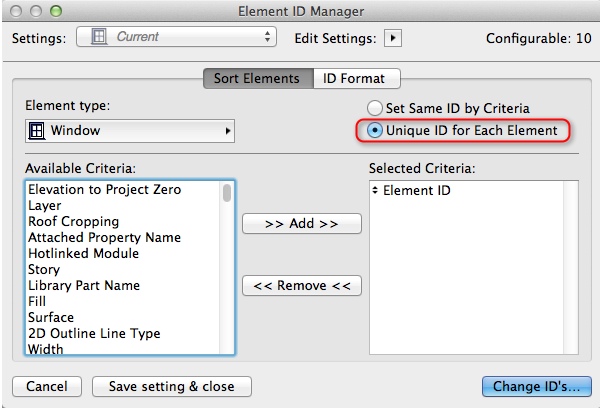
As an illustration, I’ll draw a North Pointer symbol.

All you need to do is:

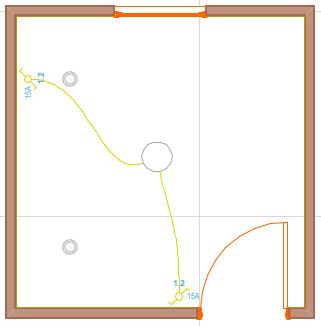
  1. Draw the 2D symbol in plan view (or any other ArchiCAD view). Use fills, lines, splines, text, etc. – any 2D documentation element will do. Be sure to add hotspots (use the Hotspot tool from the ArchiCAD Toolbox) in strategic locations. The first hotspot you place will be the default placement point for the 2D symbol. NOTE: The drawing elements should be placed on the ArchiCAD layer.
    GDLB4_01
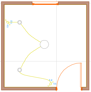
  2. Select the drawing elements, and copy (Control – C) them to the clipboard.
  3. Create a new object as outlined here
    GDLB4_02
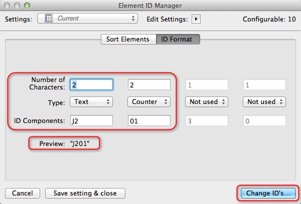
  4. Click on the 2D Symbol button, and paste (Control -V) the drawing elements into the 2D symbol window.
    GDLB4_04
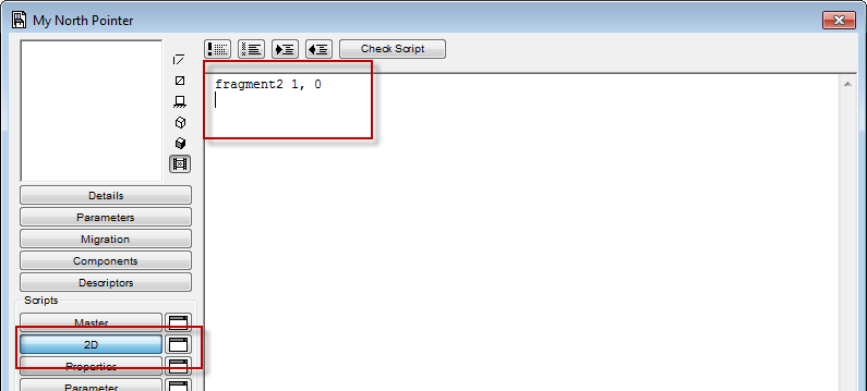
  5. Click on the 2D Script button, and type the following line of GDL code
    fragment2 1, 0
    GDLB4_05
  6. Save the object into the project’s Embedded library.

Voila! The new North Pointer object is ready to place.

Note that the object is of fixed size, and you can’t change the pens, line types, fills etc. This means that whenever it is placed, it will use the settings you used when you drew it. Which is generally a big time saver.

However you can edit the object whenever you like. The changes you made will apply to all placed instances of the object throughout your project. To edit the object:

  1. Open the library part for editing as outlined here
  2. Click on the 2D Symbol button.
  3. Edit the drawing elements.
  4. Save the object.

NOTE: One major limitation of this approach, is that no arrowheads can be included on lines or arcs. If you want to include an arrowhead, you have to draw it using a fill polygon.

Point Clouds

$
0
0

Point Clouds seem to be the latest and greatest thing these days.  They are brilliant for checking as-built against the design, or for accurately measuring an existing building for renovation.

Point clouds are produced by a scanner placed on site which measures the distance to structures  around it, giving an accurate 3D scan of the building.

We’ve produced a little add-on Cadimage point Cloud which reads in an xyz point cloud file and creates a point cloud object within ArchiCAD, available from www.cadimage.com/pointclouds

Screen Shot 2013-09-20 at 10.00.06 AM

It’s available for ArchiCAD 16 and ArchiCAD 17 on both Windows and Mac.

It is still a Beta at this stage, but try it out and let us know what you think, and what else it may require.

We have already had some great feedback, so thank you for the feedback so far.

James Hardie Brace Types

$
0
0

James Hardie has released a bunch of brace types, so now you can get achieved bracing from you Villaboard Linings, Hardiflex Cladding and even your Linea Weatherboards, as well as a bunch of other cladding types.

We have released a set of presets with these Brace types included, and also added a Brace Set which includes them all, it’s installed as part of the ArchiCAD 17 Bracing tool, just open your preset manager, click import, and browse to ArchiCAD 17/Cadimage Tools Extras/Extra Sample Presets/Extra Braces and load James Hardie.dat

Screen Shot 2013-10-24 at 3.32.39 PM

Take a note if your update to Maverick OS X 10.9

Wiggly Wires

$
0
0

The Circuit Wiring symbol of the Cadimage Electrical tool has a Wiggly option. This can help make the symbol stand out from other lines and arcs on a drawing.

ELE_Wiggles_03

Without wiggles:

ELE_Wiggles_01

With wiggles:

ELE_Wiggles_02


Element ID Manager

$
0
0

You can use the Element ID Manager to re-number the IDs of any selected elements. Just go to Document > Schedules and Lists > Element ID Manager. Then choose the settings for the element you want to change ID’s for (ie. Slab ID, Window ID etc…), then go to the ID Format tab and set the way that you want the automatic numbering to be formatted.

2013-11-11_09-40-52 2013-11-11_09-41-38

Include text when making details

$
0
0

When placing a detail marker, if you want text to be included from the source view you have to un-check Copy construction elements only in details settings dialog.

2013-11-11_09-46-08

Cutting holes in a Slab

$
0
0

To cut a hole in a Slab, select the Slab in plan view, and choose the Slab Tool in the Toolbox. Choose a Geometry Method and outline the hole.

cut-slab

Origins in ArchiCAD

$
0
0

The project origin is at 0.00,0.00.  The user origin is also at 0.00,0.00 in a new project. However when you are working it will move to your current location thus the tracker will give you relative coordinates.

2013-11-11_09-55-22

North Symbol pointing to Project North

$
0
0

If you want the ArchiCAD North Symbol object to follow the Project North, open its Settings and tick Follow Project North

2013-11-11_10-22-25

X-Y coordinates in Tracker

$
0
0

If you want to change your Tracker from Polar coordinates to X-Y Coordinates while drawing a wall ,line, slab etc. Right mouse click and select Prefer X -Y coordinates in the Tracker from the dialog.

prefer-x-y

Create an empty opening

$
0
0

If you are wanting to create an opening in a wall, simply insert a door or window the correct size.

Once positioned, select the door or window and click on the the little square icon in the Toolbar.

2013-11-11_10-27-00


This will convert the door into a simple door/window opening

2013-11-11_10-27-27


Remember to change the ID of the opening so that it wont show up in the Door/Window Schedule
Also, if you don’t want the ID marker to show up, make sure to turn it off in the settings


Calculating area by criteria

$
0
0

Double click in the ‘Navigator – Project Map’ under ‘Schedules’ on ‘Wall list’
In the newly opened window click on the Scheme settings… button in the top right hand corner

2013-11-11_11-15-42

In the Scheme settings open the Fields /Wall List tab

2013-11-11_11-16-52

You can add fields to your schedule by selecting them in the left hand column and clicking Add.
You can remove fields from the schedule by selecting them in the right hand column clicking Remove
You can also move fields Up and Down by clicking on the arrow icons

Rotating a Site

$
0
0

If you have used Cadimage Sites + Massing to create Boundaries around your site, the Cadimage Boundary objects Calculate their bearing based on Project North.

So if you are planning on Rotating your Site, you need to update Project North at the same time.

Cadimage Sites + Massing has an easy way of doing this.

From the Cadimage menu select Sites + Massing > Place North Arrow, then click for the position of your North Arrow.  A North Arrow placed this way is a Smart North Arrow and will update Project North when it is rotated.

So now select your site, all of your Boundaries, and your North Arrow, and then Rotate your Site, the Cadimage Boundary Objects will all keep their Bearing as Project North will be updated with them.

Before Rotation:

After Rotation:

ArchiCAD 17 | Real-time Cutting Planes

$
0
0

ArchiCAD now features easily manipulable 3D Cutting Planes – they can be defined graphically in your views, and then dragged/moved/rotated as you go.

image

Multiple cutting planes can be used at once, so you can click and drag them around easily to define the areas of the model that you want to isolate.

image

They’re great for quickly focussing on certain areas of your building, and because they are so easy to edit, you can quickly cut through your model to get to the are you want – whether it be a certain storey, section or junction.

Setting up your BIM server

$
0
0

ArchiCAD’s BIM server is an incredibly effective way of managing large projects and workflows within your practice.  Although it is very simple to set up, it can also be very easy to mess up.  If you are intending on setting up a BIM server please ensure that you read through and understand the instruction manual prior to installing.  If you are planning on utilising the BIM server to allow for remote users to log in, it is probably best to contact an IT specialist prior to going ahead.

We have created a document that can give you a bit more information about this here

If you do not have an IT contractor, contact your local Re-seller as they more than likely know of someone in your area that can help

XwmlZ

Importing 3DS Objects

$
0
0

Did you know that there is an Add-on available from Graphsioft that will allow you to import 3DS objects straight into ArchiCAD?

If you want to download it or any of the other available add- ons have a look here

Red-D3D-TRAREC-01

Viewing all 1008 articles
Browse latest View live