Quantcast
Channel: Tip of the Day – Cadimage Blog
Viewing all 1008 articles
Browse latest View live

Can’t Orbit

$
0
0

On very rare occasions, the Orbit control stops working. This can result in sensations of helplessness, confusion, rage and even panic. The good news is, it’s easy to fix if you know how.

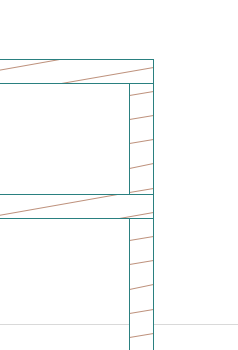
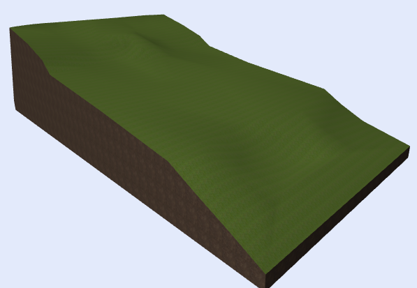
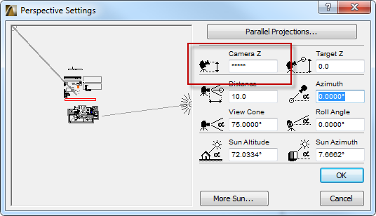
Chances are the 3D Projection Settings (in particular the Perspective Settings) have somehow gone ballistic. Sometimes this will be obvious (as in the attached image) and sometimes the settings may appear quite benign. Either way you should try the following solution.

Perspective Settings Broken 2

Close the 3D Projection Settings dialog and return to a plan view. Double-click on the Camera tool, and place a camera on the plan view.

Select the camera and generate a 3D view. You will find that the Orbit control now works.

You can delete the camera if you like.


Multiple Building Materials

$
0
0

You may find in V17 that there is potentially a need to create multiple copies of the same building material for use in different situations.

One example I discovered was Polystyrene insulation.  Even though this is the same material on site, I had to create multiple different materials with different priorities.

BMat image 1


As you can see the two types of insulation look the same, however  Plastic Soft in being cut by the concrete, and Plastic Hard is cutting the concrete.

Tip:  If you have to make multiple materials, try to describe where they should be used in the name I.E. Wood – Floor Joists, Wood – Ceiling battens etc. It will make working with your materials a lot simpler

How to Change Default Electrical Symbols

$
0
0

Each electrical component and wall plate includes a 2D symbol. The symbol can be customized to suit your office standard, and the customized symbol can become the default setting.

For instance, you might want to use one or other of these symbols (or something different) for all your double power point symbols:

Electrical_Symbols

This knowledge base article explains how to customize the default symbol.

3D document for Mid Floor framing plan

$
0
0

One of the things we get asked frequently for is the ability for walls to show over the top of beams when creating a floor framing plan.  Now thanks to the 3D Document Floor Plan display we can finally create and annotate a floor framing plan that shows exactly this. As per this image

Floor framing


I simply modelled all of the joists as beams to the correct elevation, then from the floor plan, right click and choose New 3D Document from Floor Plan…

Once the view is created, right click in the white space and choose 3D Document Settings… In the Floor Plan Projection panel, set the Cut Plane: to a height that will pass through the center of the joists:

selection settings

Differentiating between joists and blocking

$
0
0

A common frustration when using the beam tool is how to get the beams to show separately to blocking set between.  No doubt we are all familiar with this
blended beams

We can now use the Floor Plan 3D document to create tidy looking floor framing plans, (refer to this tip for guidance)
By default I get the same effect.  All I need to do now is create a new material with a lower priority.  In this case, my beams are using Timber – Structural with a priority setting of 715.  I duplicate this material name it Timber – Solid Blocking and change its priority to 700

I then select the beam I want to be blocking and change its material to be Timber – Solid Blocking, and I get the following result:

revised beams


Give it a meaning!

$
0
0

Did you know that walls can be defined in more ways than just length, height and width?

If we open the Tags and Categories section of the wall properties dialog box, we can define the Structural function as either Load Bearing or Non Load Bearing.

structural function

We can now use this information when we are looking at creating views.
Lets say for example that we need to create a Structural Plan for our engineer for a multi story office building.  He is most likely not going to be interested in our lightweight partition walls.
When we are creating the floor plans, set the Model Stucture display to show Core of Load-Bearing Elements Only

display


This can also be applied to Slab, Roofs, Columns etc..

Mesh Ridge Sharpness

$
0
0

In the Mesh tool we have 3 options under the Model Tab.
Model

If we start of with All Ridges Sharp, we can see that the mesh becomes very triangulated.

sharp
This is the simplest form for the computer to generate, but is not much good for rendering

The Second Option is User Defined Sharp,  This means that the contour lines we use will produce a sharp definition, however the ground between the contours will be smoothed out.
user deifned
This gives a better rendered finish

The third option is All Ridges Smooth.  This will smooth out the contours of the the land and give you the most realistic looking ground line effect.
smooth
This gives the best rendering finish.


Home zoom

$
0
0

Home Zoom was commonly used in previous versions of ArchiCAD & was an easy way to quickly go back to a common reference point that you predetermined.

To do this go to the 2D view you want & then from the View menu go to Zoom>Set Home View

Set Home Zoom


Now you can go to View>Zoom>Home Zoom & it will bring you back to this point.

The alternative way of course is to create a view in the view map which will do the same thing in a way most people are easily familiar with.


Setting up your mesh

$
0
0

Before we start to setup our mesh, we need to know what height to set it out to.  Have a look at your Surveyors information and find the lowest height supplied.  In my example below the lowest height contour is 50.5m

surveyor

As a rule of thumb, I always round down to the nearest whole number.  In this case I will use 50.0m
Now I go to my zero story and open up the Mesh settings. Under Geometry and Positioning, the top value I leave at 1000mm.  This is the sectional depth of the Mesh I am about to create.  Underneath that I enter in the value of 50000mm.  This will position my 1m thick Mesh 50m above sea level.
mesh settings


Don’t get too comfortable

$
0
0

One thing I find myself saying a lot when running our training courses is ‘Experiment with the program,  One of the best ways to learn is to push buttons and see what they do!’

As humans, we are by nature habitual creatures, We will find a way that works and we will keep  doing things the same way until we are forced to change.  Most people that we talk to and visit, as astounded by the power that this program has and that the only thing from holding them back from accessing the power is a reliance on old habits.

The best piece of advice here though is simply this,  If you are going to try something you have never done before, Hit Save before going ahead with it

And of course if you try something and it doesn’t work:

39204

The value of a good mouse

$
0
0

During training I often highlight the importance of getting a good mouse for your computer.

The mouse has become our main tool to complete our tasks especially when it comes to ArchiCAD.

If you were a glazier you would invest in a good glass cutter, so if you use CAD its worth getting a good mouse.

Theres lots of great options available, a popular one in the office is Logitechs ergonomic range, though there is a lot of great options out there from ones that fit the hand to ones you can even customize to fit your hand perfectly.
Try them out to see what best suits you & fits you hand shape & way of working, you may find you work with less effort & in a more comfortable way.

Mouses

Story Settings

$
0
0

When setting up your project, try to avoid using negative stories. We should have our mesh created on the Zero story and the first constructed floor goes on Story one.  The number of the Story really doesn’t matter.

Think of it this way, If we have six stories of basement that we have to create, the lowest basement story, is most likely to be the first slab poured so it goes on the first story

story settings

Door and Window Markers

$
0
0

I quite often get asked why door and window markers aren’t showing up on the floor plans.

9 times out of 10 it is simply because the person is using the wrong Model View Option.  These options allow us to display the same modelled elements in different ways.  These can range from things like Door and Window Markers, Column displays, Window sections, skylights and a whole heap more!

You can find these settings by going to Document > Set Model View > Model View Options…

MVO

As you can in this image for my MVO 03 Building Plans Markers, I have chosen to show markers for Doors, Windows and Skylights.
I can keep going though the different setting option, until I am happy, then simply hit Store As…
In the Store As… dialog box I can choose to either create a new MVO or Overwrite the existing one.
The choice is yours!

For those of you not familiar with the use of MVO’s, take some time to read up on it in your ArchiCAD help manual as they can save you an awful lot of time!

Open doors in Fly-Through

$
0
0

You now already from a previous post how to enable the ‘doors opening in animation’:

http://blog.cadimage.com/2010/09/tip-of-the-day-18062008/

Remember to enable to ‘Rebuild the model for each frame’ of the rendering process.

17-01-2014 7-56-18 a-m-01

Electrical model view combination

$
0
0

If  you want to have a model view combination for an electrical plan, you can load it from the Cadimage extras folder located in:

\GRAPHISOFT\ArchiCAD 17\CadimageTools Extras\Electrical

17-01-2014 5-10-18 p-m-01


17-01-2014 5-13-55 p-m-01


Assist your QS

$
0
0

Since you have build a perfect 3D representation of the proposed building it seems a waste of time for the Quantity Surveyor to take a scale ruler to a set of 2D drawings to figure out quantities.

ArchiCAD can find out anything about all the elements in your project using the interactive schedule, it may save time & money to assist your QS with accurate values from your model to put costing to. For examples how about the floor finishes of all the rooms using Zones? :

Floor Finishes Schedule


To get set up & understand how to start creating your own detailed Interactive Schedules heres a great guide: http://helpcenter.graphisoft.com/guides/archicad-17-int-reference-guide/virtual-building/archicad-model-views/interactive-schedule/

It goes through 10 short pages about all the features & capabilities, by the end of that you may save yourself hours & $ in producing more accurate detailed schedules.

Create a floor finishes schedule

$
0
0

If you have placed Zones in your Building using specific cover fills, you can create a simple Floor Finishes Schedule by using the following settings.

First create a new Schedule, Document>Schedules & Lists>Schedules>Scheme Settings…

Click Create New and enter in the settings as shown below:
Floor finishes

This will give you a result that looks like this:

Floor finishes 2


This list can then either be saved as a view and then printed out, or it can be saved out as an Excel Spreadsheet and then given to your Quantity Surveyor.


Open and Repair

$
0
0

Do you have a corrupt file?

The new Open & Repair function is available in the Open dialogue. This function can fix v17 damaged pln files in certain cases.

ArchiCAD 17 introduces a new feature that will enable you to repair a corrupt file.

Just go to File>open>open> enable the box ‘Open and repair’ , finally select the file and click Open

21-01-2014 5-02-53 p-m-01


Add custom colors to the color pallete

$
0
0

If you are editing a surface color or a pen, you may want to have a range of custom colors in the palette.

You must select the custom pen box and then edit it, finally click ‘add to custom colors’


29-01-2014 9-48-09 a-m-05

28-01-2014 5-26-34 p-m-01

Add attributes for Plant objects

$
0
0

If you search a plan object from Cadimage in BIMComponents you may need to add the attributes for the plants to your project to display the surfaces correctly.


4-02-2014 5-11-59 p-m-01


To enable the attributes in your file you can download the attributes file (Phormium Materials) from :

http://cadimage.com/mycadimage/downloads/goodies

1. Then open the attribute manager> surfaces.
2. Open the file
3. Select the attributes and click << Append
4. Apply the changes and click Create.

4-02-2014 4-57-40 p-m-01


4-02-2014 4-57-59 p-m-02

Viewing all 1008 articles
Browse latest View live